| T O P I C R E V I E W |
| DigiSnapMark |
Posted - 16 May 2018 : 22:17:44
Whew, this is a new one to me. I've been using Pulsonix for about a decade. Currently at V8.5, 5900.
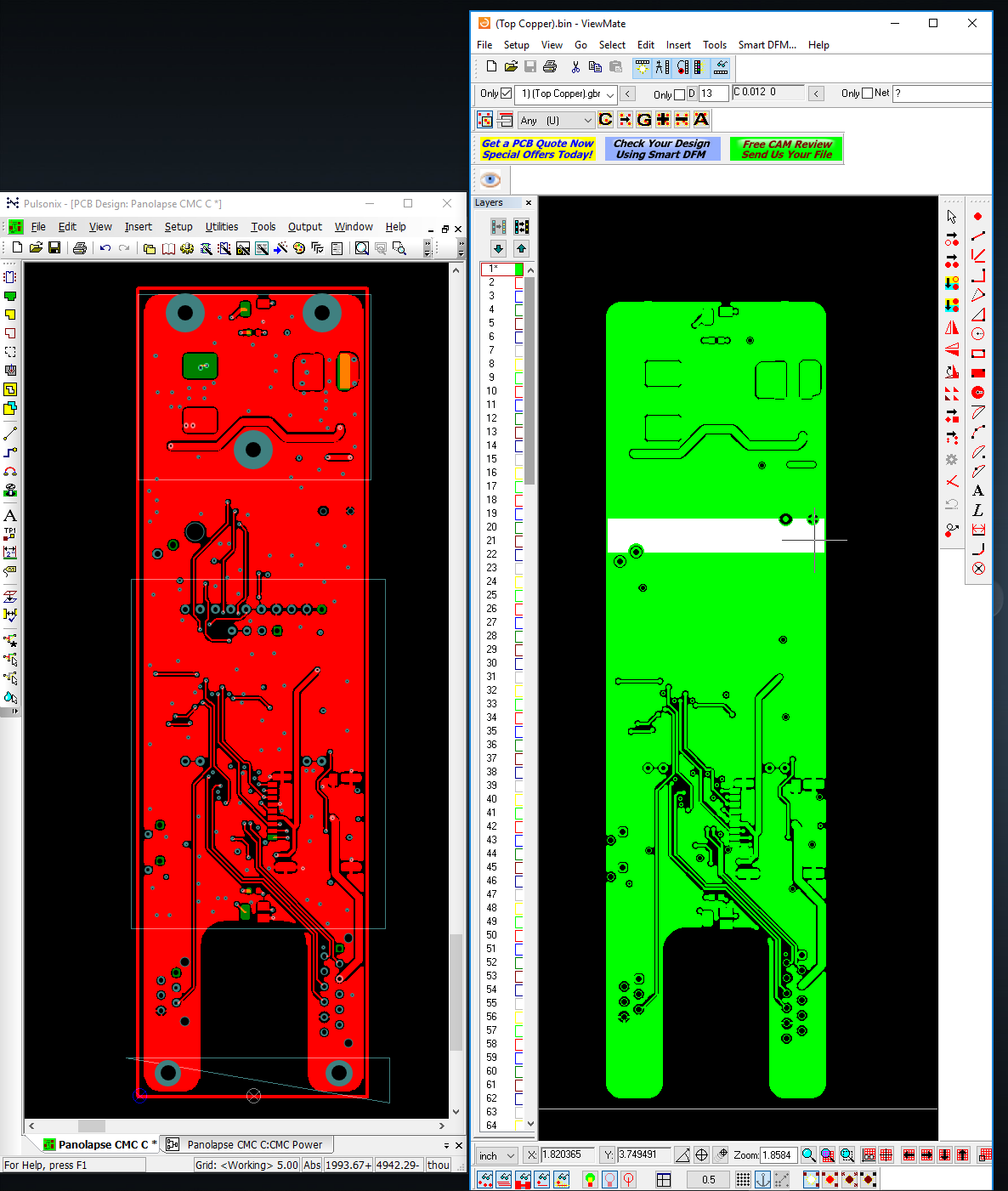
The design looks fine on screen, plot preview, DRC, you name it. But when I generate the plot, there is a section on the top layer Gerber that is filled. It's selective though, in that there are a few vias that aren't shorted. The other layers look OK at first glance.
Of course I (and Gold Phoenix) didn't catch this until I built a couple boards and noticed all the pins where shorted to ground. Sigh...
If I don't pour the ground plane template, the plot is clean. It doesn't matter if I plot the layer independently of all the others. I can't find anything in the design that spans that area, and again the design and plot previews look OK.
I've attached a picture of the design, and the plotted Gerber. I've attached the gerber file as well in hopes that someone can see what the heck is happening. A problem like this immediately causes me to lose confidence in my place in the world!
Image Insert:
156.51 KB
Download Attachment:  (Top Copper).gbr (Top Copper).gbr
62.05 KB |
| 11 L A T E S T R E P L I E S (Newest First) |
| steve |
Posted - 21 May 2018 : 09:10:48
Without data, we are unable to say if an expected problem, as that pictured, had or had not been investigated back in 2015, all we can say is that when customers raise such a question, we investigate immediately and act accordingly, under the conditions we publish. If we identify a problem, then we will issue a fix in a product update. We strongly recommend that you keep your software up-to-date by installing every update that is issued so that you take advantage of all the latest fixes for any critical issues.
We recommend, as stated in our Help, that outputs are checked before manufacture. We do not recommend loading the outputs back into Pulsonix using either of the Gerber import tools we provide, this is not their intended use.
Board manufacturers can also provide checking, including for opens and shorts, prior to manufacture.
Pulsonix Assistance |
| jameshead |
Posted - 19 May 2018 : 22:37:34
I've been using a recent still free version of GC-Prevue to check Gerbers prior to sending them out. GC-Prevue also has a good feature in the "mix" draw function where you can load in two differnet gerber files of the same board, example an issue 1 and issue 2, make them different colours, then see easily where the changes have been applied.
I have seen issues with Gerber outputs before that have been the fault of the import process to the Gerber viewer and not the fault of the Gerber output from Pulsonix or other CAD Tool, and I've seen errors in Gerber outputs from other CAD tools including Cadstar, PADS, Altium Designer over the years.
Thankfully these days we have Gerber-X2 and RS-274X but I remember importing RS-274 and having to manually enter, sometimes very long, aperture tables. This could be an error-prone process! |
| cioma |
Posted - 19 May 2018 : 13:57:01
Well, I prefer to use an independent CAM tool (FAB3000 in my case) to check manufactured data because if you use the same CAD tool (Pulsonix) for data generation and data check you are less secure as it's likely to be written by the same people using the same libraries therefore would likely to have the same or similar bugs that might mask the issue.
I believe there are release files that describe fixed issues between Pulsonix version in question and later versions so it's possible to figure out if this particular issue was fixed. |
| Chris |
Posted - 19 May 2018 : 09:34:42
I had the same problem in Version 9. From Pulsonix i got a fix with build 6602. After that i did not met this problem, but it stays tricky if you can't rely on the generated gerber data.
I got the advise to reload the generated gerber data with a small offset and with switched off 'translucent Copper'. By doing this you can see all the differences between your design data and the generated gerber data... but it's a lot of work.
Maybe we need such an advise with Pulsonix but on the other hand it's to be ashamed for Pulsonix that it produces gerber data you can't rely on.
For us it has cost a lot of money for something that i was never worried about before with other CAD systems.
Pulsonix has to make a tool with one button that compares the generated geber data with the design data and warns if there are difference... or maybe an automatic check after generating gerber data
|
| DigiSnapMark |
Posted - 18 May 2018 : 17:36:33
Maybe we fixed it, maybe not. That's the official response from Pulsonix?
|
| steve |
Posted - 18 May 2018 : 16:27:18
As the software you are using had eight patch releases after the version you are using and has since moved onto two other versions, this may have been investigated at the time of the release you are using.
Pulsonix Assistance |
| DigiSnapMark |
Posted - 18 May 2018 : 16:06:15
The plot parameters are the same I've used in all the other layers, indeed most of the designs I've created over the last decade.
My software dealer wasn't able to reproduce this, using the latest version of software. My version is admittedly a year old, but this seems like a rather critical feature, so I'm still hoping one of the development team will have a look.
I am of course trying to isolate the issue on my own as well, and have shrunk the template around the affected area. For some reason I can't upload a picture... If any edge of the template is moved to the center by as much as 5 tho, the pour is implemented correctly. There are no parts centered in that space on that layer, and the edges of the template don't seem particularly aligned on any particular feature.
Very frustrating not to understand why the program is generating CRAP, as this means I can't have confidence that it'll work in the future. |
| cioma |
Posted - 18 May 2018 : 10:47:14
At last I was able to download the Gerber file and I can confirm it looks the same in FAB3000 as in your ViewMate.
So for some reason part of the layout in the middle of the board didn't produce correct Gerber artwork (pads, traces and vias). What are your CAM plot parameters for Gerber?
Indeed generating IPC-D-356 netlist and asking your manufacturer to check both imported data and bare board against it is a very good idea. |
| DigiSnapMark |
Posted - 17 May 2018 : 15:50:11
James, excellent suggestion, I will try that with further submissions to board vendors.
|
| cioma |
Posted - 17 May 2018 : 09:24:40
It seems I can't download this file |
| jameshead |
Posted - 17 May 2018 : 00:42:19
I haven't had a close look at your gerber yet - it's late in the UK now.
I would say though that in over 20 years of PCB Engineering, sitting at the CAM import end at a PCB fabricator as well as the CAD output end as a PCB Designer, I've seen errors in the gerber caused from both the PCB CAD output and the PCB CAM import software.
What I recommend is you output an IPC-D-356 netlist, from the OUTPUT / REPORTS menu in Pulsonix, and send that to your fabricator along with the ODB++ file in addition to the Gerber - and tell your fabricator to use this netlist for checking the imported gerber against the design-intent, and also against the fabricated PCBs; and not to create their own netlist from the imported Gerber. This would probably have caught your problem before any PCBs were fabricated.
If you have any internally connected components (such as SOT-223s) or intentional short circuits such as star points you should tell the fabricator because these will flag up as errors between the netlist and gerber. |
|
|