I am making slotted holes for DC plug, Everything looks normal in PCB editor, but when i am trying to make a plot, Pulsonix won't plot slotted drill holes. I made slotted hole using "Define Pad Shape" option. I tried to use defined pad style : "Slotted Oval(50x70)" but it won't plot drill hole also!
Are you referring to an Excellon output or Gerber file output?
In Outputs > CAM/Plot you should find that when you select your Drill file and press the Edit button, then go through the dialogue then the second page "Output" has drop-down selection boxes. The one named Hole Shape: should be All if you want both Round and non-Round (Slots) in the same output file.
It's better to include your slots in a separate drill file though for clarity when communicating with some PCB Fabricators. So if you had both plated and non-plated slots and holes you could end up with four drill files:
Plated normal drill Non-Plated normal drill Plated Slots Non-Plated Slots
I have the same problem in both formats - gerber and excellon.
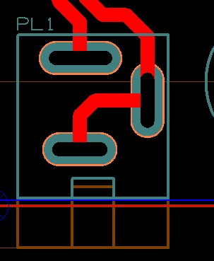
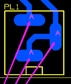
It looks like, pulsonix is making empty drill hole. When i send gerber files to manufacturer they said that i a missing the slot holes. And send this picture.
Image Insert: 13.22 KB
And this is what is shown in Window -> Plot -> Drill Sizes. Should there be 0.0 for diameter?
You should see "Special" for the size in the Drill Hole column for a slot if you are viewing the pad styles in Edit Technology.
In the PCB file, Slots will show as the size in the Diameter column under Drill Sizes in Edit Technology, e.g. 1.000X4.200. The symbol column and symbol size column are just what will be used to represent the drill in the drill drawing - which is reference drawing only. You can make it what you want. It doesn't affect the drill size.
If you edit the footprint, use File SAVE AS you can save the footprint as a separate file and upload it to the forum.
You don't need to use Define Pad Shape to create a slotted drill.
You can create a normal oval pad, and select Oval next to shape for the Drill part in Edit Technology without having to use Define Pad Shape.
I've uploaded the symbol, footprint, and part for a Cliff DC-10A that I created in my library some time ago.