Pulsonix TRM Thermal Analysis (PDM)
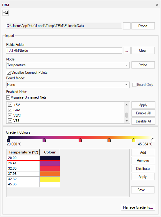
Pulsonix TRM Interface
With boards and parts becoming smaller, components and electrical currents heat your board making thermal issues a major threat to the integrity of your product.
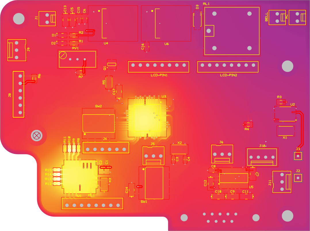
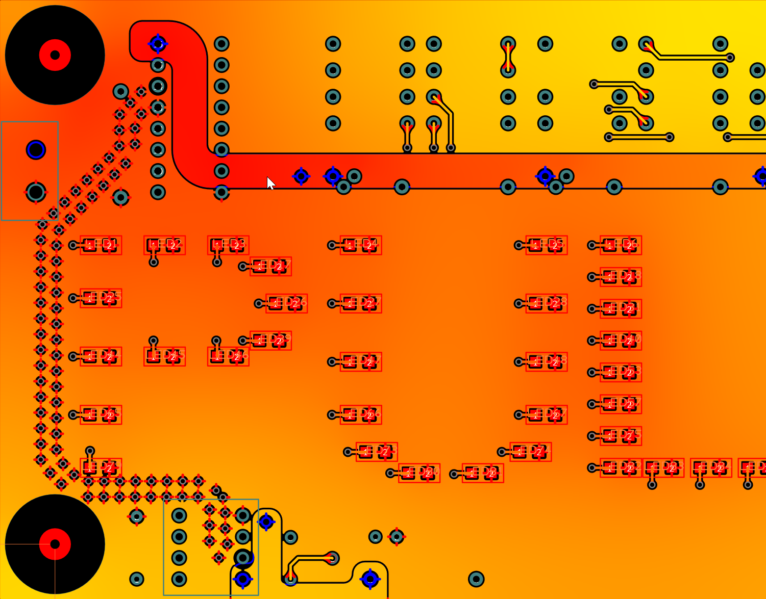
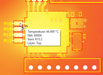
TRM is a field simulation software tool that calculates the expected temperature of a printed circuit board in detail based on currents and/or component heating and its cooling to ambient. It runs and displays thermal and electrical analysis (PDN) in an easy-to-use, flexible and powerful toolset.
Below is a quick view of the TRM Interface highlights. For more information view the Pulsonix TRM datasheet.

Board, Component & Current Analysis
The 3D differential versions of potential and heat equations are solved; Currents are DC currents
which are fed in and out via plugs or on pads, electricity and component heat diffuses in the panel
and is transferred to the ambient air via a flat-rate heat transfer coefficient. This coefficient
also contains the proportion of radiation.
Pulsonix TRM Interface
Pulsonix uses an integrated interface to collate all the design information required such as all layer structures including layer materials, tracking, copper areas, component data and net data which are all passed into TRM ready for simulation. No complicated data collection or scripts required, this is all taken care of using the Pulsonix TRM interface.


